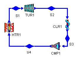
Figure 1: a typical Brayton Cycle

Figure 1: a typical Brayton Cycle
We will start by constructing a typical Brayton cycle which we will use to judge the effects of our proposed changes. A Brayton cycle is the air-standard analog of the Rankine cycle. As such, its turbines and compressors are isentropic and adiabatic and its heaters, coolers, and heat exchangers are isobaric.
The example Brayton cycle (bray1.dsn)to which we will compare has the following parameters:
We will compare the efficiencies of our modified Brayton cycles to these to see if the modifications have improved the cycle.
Figure 2 shows the T-s diagram for our example Brayton Cycle. We notice two things about this cycle. First, during the cooling process, we are throwing away quit a bit of heat. The second is that not all of the heat addition and rejection is at (or even near) the maximum and minimum cycle temperatures. We will look at each of these issues in turn.
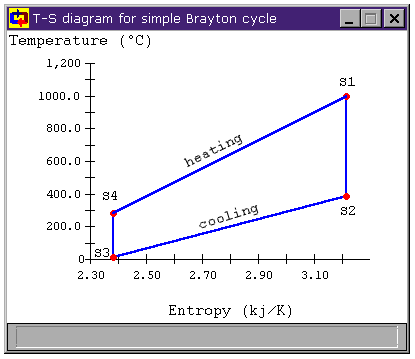
Figure 2: Brayton Cycle T-s Diagram
and the average temperature of heat rejection is
Using these mean temperatures, we can find the cycle's thermal efficiency by applying the relation for Carnot efficiency to the mean cycle temperatures:
Which will give same answer we get applying the usual hth = Wnet / Qhi relation.
For more efficient cycles, we would like to add heat at a higher temperature and reject it at a lower temperature. Obviously, if we could add all of our heat at the maximum cycle temperature and reject all of it at the minimum cycle temperature, our cycle's efficiency would equal the Carnot efficiency.
For instance, Table 1, shows these parameters in the simple Brayton cycle we have just considered.
| Maximum Cycle Temperature | 1000°C |
| Mean Temperature of Heat Addition | 592.7°C |
| Minimum Cycle Temperature | 15°C |
| Mean Temperature of Heat Rejection | 175.3°C |
| Carnot Efficiency | 77.37% |
| Thermal Efficiency, hth | 48.21% |
| Table 1: Efficiency Parameters for simple Brayton Cycle | |
|---|---|
We are adding heat at a much lower temperature (over 400°C lower) than the maximum cycle temperature. At the other end, we are removing heat from the system at 160°C above the minimum cycle temperature. We will now examine some modifications to the basic cycle and see if we cannot bring these numbers closer to the ideal.
| T1 = 1000°C | |
| T2 = 386°C | |
| T3 = 15°C | |
| T4 = 283°C |
This seems to indicate that we can use the heat thrown out between S2 and S3 that is above 283°C to do some heating between S4 and S1. To take advantage of this potential heat, we add a heat exchanger to our cycle. Figure 3 shows the addition of such a heat exchanger (bray1x.dsn).
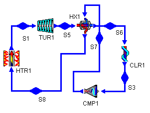
Figure 3: Brayton Cycle with
Heat Exchanger

Figure 4: Brayton Cycle with Heat Exchanger
T-s diagram
| This Cycle | Simple Brayton | |
| Maximum Cycle Temperature | 1000°C | 1000°C |
| Mean Temperature of Heat Addition | 659.7°C | 592.7°C |
| Minimum Cycle Temperature | 15°C | 15°C |
| Mean Temperature of Heat Rejection | 134.5°C | 175.3°C |
| Carnot Efficiency | 77.37% | 77.37% |
| Thermal Efficiency, hth | 56.30% | 48.21% |
| Table 2: Brayton Cycle with Heat Exchanger Efficiency Parameters | ||
|---|---|---|
Examining the heating and cooling for the modified cycle in Figure 4, we can see that all of the heat transfer between S5 and S6 that was formerly thrown out in the cooler is now used to heat the fluid from state S7 and S8. Because of this, we are now only adding new heat to the cycle between S8 and S1, raising the mean temperature of heat addition. Similarly, we are now only removing heat from the cycle between S6 and S3, lowering the mean temperature of heat rejection. The result is that the cycle efficiency has risen substantially.
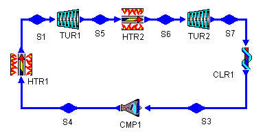
Figure 5: Brayton Cycle with Reheat Stage
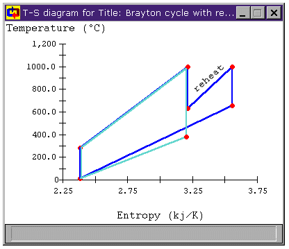
Figure 6: Brayton Cycle with Reheat Stage
T-s diagram
| This Cycle | Simple Brayton | |
| Maximum Cycle Temperature | 1000°C | 1000°C |
| Mean Temperature of Heat Addition | 654.7°C | 592.7°C |
| Minimum Cycle Temperature | 15°C | 15°C |
| Mean Temperature of Heat Rejection | 274.7°C | 175.3°C |
| Carnot Efficiency | 77.37% | 77.37% |
| Thermal Efficiency, hth | 40.96% | 48.21% |
| Table 3: Brayton Cycle with Reheat Efficiency Parameters | ||
|---|---|---|
However, the cycle efficiency of the modified cycle has actually decreased by over 7%. Why is this? Looking at Figure 6, we can see not only that the mean temperature of heat addition has increased, but also that the mean temperature of heat rejection has increased. So, while the the former increases efficiency, the latter decreases it. In this case, the net effect is a decrease in cycle efficiency (and a large decrease at that!).
To bring the average temperature at which we remove heat to the cycle closer to the lowest temperature, we can add an intercooling stage to the cycle. Figure 7 shows the addition of such a stage to a Brayton cycle (bray1i.dsn). Analogous to the reheat stage, the intermediate pressure for the intercooler is 300 kPa, giving each compressor roughly equal pressure ratios.
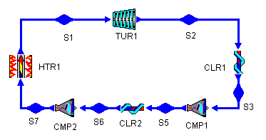
Figure 7: Brayton Cycle with Intercooling
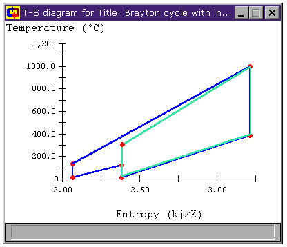
Figure 8: Brayton Cycle with Intercooling
T-s diagram
| This Cycle | Simple Brayton | |
| Maximum Cycle Temperature | 1000°C | 1000°C |
| Mean Temperature of Heat Addition | 485.9°C | 592.7°C |
| Minimum Cycle Temperature | 15°C | 15°C |
| Mean Temperature of Heat Rejection | 145.0°C | 175.3°C |
| Carnot Efficiency | 77.37% | 77.37% |
| Thermal Efficiency, hth | 44.90% | 48.21% |
| Table 4: Brayton Cycle with Intercooling Efficiency Parameters | ||
|---|---|---|
However, as we saw with the addition of a reheat stage, the cycle efficiency of the modified cycle has once again decreased. Again, though we have met our objective of decreasing the mean temperature of heat rejection, it is also clear that the mean temperature of heat addition has decreased as well, having a negative impact on cycle efficiency.
The reheat and intercooling stages have their places, though. When we added a heat exchanger to the Brayton cycle, we took advantage of waste heat being thrown away in the cooler and used it to provide heat that would be used in the turbine. However, we were limited by the temperature difference between the air leaving the turbine and the air leaving the compressor. For our example, that temperature difference was about 100°C. The larger that temperature difference, the more heat we can grab from the cooling process and inject into the air before it enters the heater and the greater portion of our added heat is near the maximum cycle temperature.
Can we make that temperature difference greater? When we look at the T-s diagrams in Figure 6 and Figure 8, we see that the difference in temperature between the air leaving the compressor and the air leaving the turbine in either cycle is larger than it was for the unmodified Brayton cycle in both cases. Below, Figure 9 shows the T-s diagram for a cycle with both intercooling and reheating (bray1ri.dsn). For reference, the unmodified Brayton cycle's T-s diagram is shown in light green. Also shown is the temperature difference for the unmodified Brayton cycle DT1 and the temperature difference of the cycle with both intercooling and reheat stages DT2. We can see that the latter is much greater. In fact, whereas DT1 is about 100°C, DT2 is over 500°C!
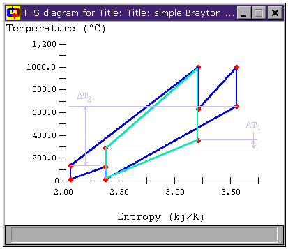
Figure 9: Brayton Cycle with both
Reheat and Intercooling T-s diagram
| This Cycle | Simple Brayton | |
| Maximum Cycle Temperature | 1000°C | 1000°C |
| Mean Temperature of Heat Addition | 559.6°C | 592.7°C |
| Minimum Cycle Temperature | 15°C | 15°C |
| Mean Temperature of Heat Rejection | 230.4°C | 175.3°C |
| Carnot Efficiency | 77.37% | 77.37% |
| Thermal Efficiency, hth | 39.52% | 48.21% |
| Table 5: Brayton Cycle with Reheat and Intercooling Efficiency Parameters | ||
|---|---|---|
We note that the thermal efficiency of this cycle is still worse than that for the basic Brayton cycle (in fact, it's worse than for the cycles with only reheat or intercooling as well). However, we can take advantage of the larger temperature difference with a heat exchanger. This new cycle (bray1rix.dsn) is shown below in Figure 10.
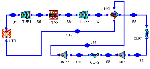
Figure 10: Brayton Cycle with Reheat, Intercooling,
and Regererative Heat Exchange
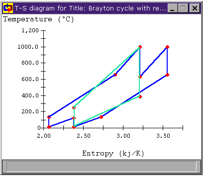
Figure 11: Brayton Cycle with Regeneration,
Reheat, and Intercooling T-s diagram
| This Cycle | Simple Brayton | |
| Maximum Cycle Temperature | 1000°C | 1000°C |
| Mean Temperature of Heat Addition | 811.3°C | 592.7°C |
| Minimum Cycle Temperature | 15°C | 15°C |
| Mean Temperature of Heat Rejection | 68.2°C | 175.3°C |
| Carnot Efficiency | 77.37% | 77.37% |
| Thermal Efficiency, hth | 68.51% | 48.21% |
| Table 6: Brayton Cycle with Regeneration, Reheat, and Intercooling Efficiency Parameters | ||
|---|---|---|
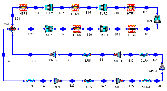
Figure 12: Brayton Cycle with Regeneration, Reheat, and Intercooling
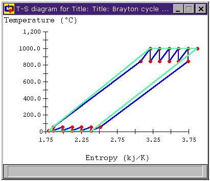
Figure 13: Brayton Cycle with Multiple Stages of
Regeneration, Reheat, and Intercooling T-s diagram
| Number of Turbines | Simple Brayton |
1 | 2 | 3 | 4 | 5 |
| Maximum Cycle Temperature | 1000°C | |||||
| Mean Temperature of Heat Addition | 592.7°C | 659.7°C | 811.8°C | 870.1°C | 900.9°C | 920.0°C |
| Minimum Cycle Temperature | 15°C | |||||
| Mean Temperature of Heat Rejection | 275.3°C | 134.5°C | 68.0°C | 49.0°C | 40.2°C | 34.8°C |
| Carnot Efficiency | 77.37% | |||||
| Thermal Efficiency, hth | 48.2% | 56.3% | 68.6% | 71.8% | 73.3% | 74.2% |
| Table 7: Brayton Cycle with Multiple Regeneration, Reheat, and Intercooling Stages Efficiency Parameters | ||||||
|---|---|---|---|---|---|---|
There are two reasons. First, in keeping with our overall goal of improving cycle efficiency, we want the mean temperature of heat addition to be as high as possible and the mean temperature of heat rejection to be as low as possible. It turns out (and this can be shown with a little math) that we achieve this by keeping the PRs of the turbines even.
The other reason is a purely pragmatic design consideration. If we are going to order turbines, larger ones tend to be more expensive than smaller ones (both in initial cost and in overhead for physical space and maintenance). The same will tend to be true of compressors.
Figure 14 below shows the effect of varying the turbine outlet pressure on the thermal efficiency of the cycle for a two stage plant. We note that the efficiency peaks when the outlet pressure of the first turbine is about 316 kPa, which gives both turbines PRs of 3.16.
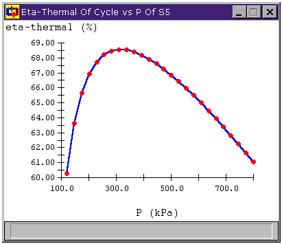
Figure 14: Cycle efficiency vs. turbine outlet pressure
Haywood, R.W. 1980. Analysis of Engineering Cycles. Pergamon Press. ISBN: 0-08-025440-3
Van Wylen, Sonntag, Borgnakke. 1994. Fundamentals of Classical Thermodynamics, 4th Ed. John Wiley and Sons. ISBN: 0-471-59395-8
Go to


or

Contributed by: M. E. Brokowski
Initial Entry: 02/02/1998
Last Edited: 03/04/1998
For comments or suggestions please contact CyclePad-librarian@cs.northwestern.edu