 CyclePad
Design Library
Design of an Otto Cycle
Goal
We look at the design of an Otto cycle and at how its performance can be improved by changing its volumetric compression ratio. The Otto cycle a closed cycle (where the system is a control mass), commonly used to model the cylinders of spark-ignition, internal combustion, automobile engines, i.e. gasoline engines.
The General Idea
The Otto cycle is very similar to the Diesel cycle in that both are closed cycles commonly used to model internal combustion engines. The difference between them is that the Otto cycle is a spark-ignition cycle instead of a compression-ignition cycle like the Diesel cycle. Spark-ignition cycles are designed to use fuels that require a spark to begin combustion.Stages of Otto Cycles
Otto Cycles have four stages: expansion, cooling, compression, and combustion.
|
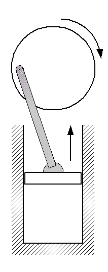
Expansion:In the Otto cycle, fuel is burned to heat compressed air and the hot gas expands forcing the piston to travel up in the cylinder. It is in this phase that the cycle contributes its useful work, rotating the automobile's crankshaft. We make the ideal assumption that this stage in an ideal Otto cycle is isentropic.Piston: moving from bottom dead center to top dead center. |
|
|
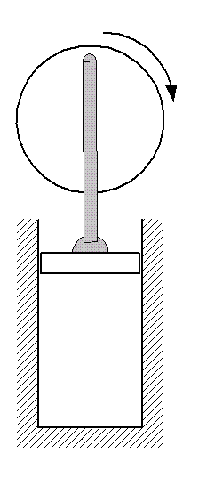
Cooling:Next, the expanded air is cooled down to ambient conditions. In an actual automobile engine, this corresponds to exhausting the air from the engine to the environment and replacing it with fresh air. Since this happens when the piston is at the top dead center position in the cycle and is not moving, we say this process is isochoric (no change in volume).Piston: at top dead center. |
|
|
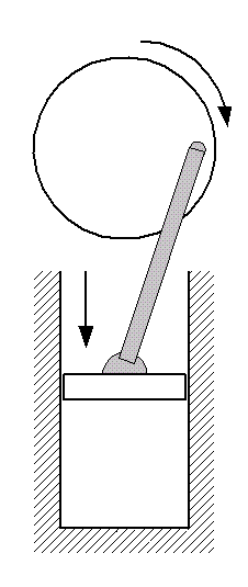
Compression:In preparation for adding heat to the air, we next compress it by moving the piston down the cylinder. It is in this part of the cycle that we contribute work to the air. In the ideal Otto cycle, this compression is considered to be isentropic.It is at this stage that we set the volumetric compression ratio, r which is the ratio of the volume of the working fluid before the compression process to its volume after. It will turn out that the efficiency of the Otto cycle (assuming that air is an ideal gas) can be described entirely in terms of this ratio. Piston: moving from top dead center to bottom dead center. |
|
|
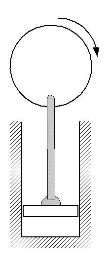
Combustion:Next, heat is added to the air by fuel combustion when the piston is at it bottom dead center position. Combustion is not initiated until a spark (from a spark plug, for instance) is generated in the cylinder. Because the piston is essentially immobile during this part of the cycle, we say that the heat addition is isochoric, like the cooling process.Piston: at bottom dead center. |
P-v Diagram
The P-v diagram for an Otto cycle is shown below.
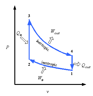
Figure 5: Otto Cycle P-v diagram
Example Otto Cycle Design
Problem Statement
For purposes of illustration, we will assume that we want to design an Otto cycle that takes 1kg of air at ambient conditions of 15°C and 100kPa, compresses it to one-eighth its original volume and adds 1800kJ of heat to it in its combustion process. With what we know about Otto cycles, that is all we need to completely describe the problem.
CyclePad Implemention
Below is a possible CyclePad design of an Otto cycle.

Figure 6: Otto Cycle in CyclePad
the working fluid
We the most common working fluid for an Otto cycle is air, since it is the cheapest thing in which to burn gasoline. We can choose air as our working fluid as air by selecting it as the substance in the meter window of any stuff.
Description of Cycle Stages
We will briefly examine each statepoint and process of the Otto cycle where design assumptions must be made, detailing each assumption. As we can see from the example design constraints, very few numbers need be specified to describe an ideal Otto cycle. The rest of the assumptions are determined by applying background knowledge about the cycle. The principle numerical design decision is the compression ratio.
Cycle Properties
Under the Cycle menu item, we can call up the Cycle Properties meter window. The only needed assumption here is that the cycle is a heat engine (a device to convert heat to work) so that CyclePad knows how to evaluate its efficiency.
Pre-Expansion (S1)
No necessary specifications here, although it is as good a place as any to specify the working fluid to be air.
Expansion Process (EXP1)
Since we are analyzing an ideal Otto cycle, we assume that the expansion is isentropic. If we knew how much heat loss occurred in the expansion and the work it produced, we might be able to specify those here instead to model a non-ideal expansion process.
Exhaust (Post-Expansion) (S2)
No necessary specifications here. This is where we release the used air to the environment.
Cooling Process (CLG1)
Since the replacement of spent air with fresh air occurs when the piston is at its top dead center position, we assume the cooling process to be isochoric.
Pre-Compression (S3)
At this point, we have air entering the cylinder at ambient conditions, so we assume the temperature t be 15%deg;C and the pressure to be 100 kPa, as specified in the problem statement.
Compression Process (CMP1)
Here we assume both that the compression for out ideal Otto cycle is isentropic and that our compression ratio is 8, as given in the problem statement.
Post-Compression (S4)
No necessary specifications here.
Combustion Process (HTG1)
Here we assume that the heating (which takes place while the piston is at bottom dead center and not moving, similar to the cooling) is isochoric and we also assume the heat added (Q) to be 1800 kJ.
Otto Cycle Efficiency
We can look again in the Cycle Properties meter window to see that the thermal efficiency of the Otto cycle we have built is about 57.5%.
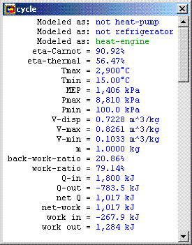
Figure 7: Cycle Properties
| h = |
|
= 1 - 1/(rk-1) |
So we can improve the cycle's efficiency by increasing the compresion ratio. The following figure shows the relation graphically.
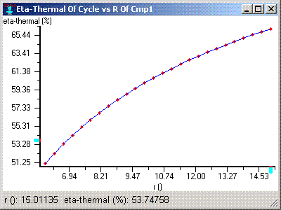
Figure 8: Cycle Efficiency vs. Volumetric Compression Ratio
This begs the obvious question: Why not set the compression ratio to something very large to get the highest efficiency? The answer is twofold. First, our compression ratio is limited by mechanical constraints in the system. If the pressure in the cylinder is too high, the chance of breaking the piston, the cylinder, or some other part of the engine. For example, bearings are prone to failure in automobile engines run with overly high compression ratios. The plot below shows the relationship between maximum cycle pressure and the compression ratio.
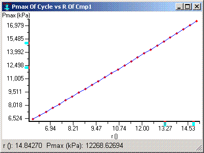
Figure 9: Maximum Cycle Pressure vs. Volumetric Compression Ratio
In addition, as we increase the compression ratio, the increased pressure and temperature after the compression process increases the likelihood of dieseling, which describes a situation in which the fuel ignites on its own, before the ignition spark is applied. This conflicts with our assumption that ignition (and thus combustion) takes place when the piston is at the isochoric bottom dead center position. In addition, it can actually result in engine damage where the combustion takes place even before the piston has finished getting through the compression process and forces the piston backup before the crank shaft has rotated to the proper position (before it has gone from the orientation shown in figure 3 to the one in figure 4).
CyclePad Design Files
Download the CyclePad design of the Otto cycle.
Related Entries
Sources
Whalley, P.B. 1992. Basic Engineering Thermodynamics. Oxford University Press. ISBN: 0-19-856255-1
Van Wylen, Sonntag, Borgnakke. 1994. Fundamentals of Classical Thermodynamics, 4th edition. John Wiley and Sons. ISBN: 0-471-59395-8
Contributed by: M. E. Brokowski
Initial Entry: 11/21/01
Last Edited: 03/13/02
For comments or suggestions please contact CyclePad-librarian@cs.northwestern.edu
