Problem CP1 (based on 2-46)
A rigid tank with a volume of 2.5m3 contains 5kg of saturated liquid-vapor mixture of water at 75°C. Now the water is slowly heated.
Now change the heating process to a constant-pressure process.
Problem CP2 (based on 2-69)
The pressure in an automobile tire depends on the temperature of the air in the tire. When the air temperature is 25°C, the pressure gage reads 210 kPa. Assume the atmospheric pressure to be 100 kPa.
Chapter 3
Problem CP3 (based on 3-35E)
A frictionless piston-cylinder device initially contains 12 lbm of superheated water vapor at 60 psia and 500°F. Steam is now cooled at constant pressure until 70 percent of it, by mass, condenses.
Problem CP4 (based on 3-46)
A piston-cylinder device with a set of stops contains 10 kg of refrigerant 134a. Initially, 8 kg of the refrigerant is in the liquid form, and the temperature is -8°C. Now heat is transferred slowly to the refrigerant until the piston hits the stops, at which point the volume is 400 L.
Chapter 4
Problem CP5 (based on 4-30)
Steam enters an adiabatic turbine at 10MPa and 400°C and leaves at 20kPa with a quality of 90 percent.
Neglecting the changes in kinetic and potential energies, determine the mass flow rate required for a power output of 5 MW.
How does the required mass flow change if we alter the dryness at the outlet? Why? (hint: do a sensitivity plot)
Retrieve assignment problem file CP5.PRB.
Directions on how to submit this (.PRB) type of problem (NOTE: CP5-CP8 are different from CP1-CP4.)
Problem CP6 (based on 4-58)
We have 8kg/min of Refrigerant 134a at 800 kPa, 70°C, which we need to condense into a saturated liquid at the same pressure. We cool it using water which enters the condenser at 300 kPa and 15°C and leaves at 30°C at the same pressure. (Hint: build this using a heat exchanger with isobaric hot and cold legs.)
Retrieve assignment problem file CP6.PRB.
Directions on how to submit this (.PRB) type of problem (NOTE: CP5-CP8 are different from CP1-CP4.)
Problem CP7 (based on 4-16)
(You will need to make sure CyclePad is considering velocity to do this problem. Do this in the Edit -> Preferences menu under the "Advanced" settings.)
Steam at 3 MPa and 400°C enters an adiabatic nozzle (throttle) steadily at 40 m/s and exits at 2.5 MPa and 300 m/s.
Retrieve assignment problem file CP7.PRB.
Directions on how to submit this (.PRB) type of problem (NOTE: CP5-CP8 are different from CP1-CP4.)
Chapter 6
Problem CP8 (based on 6-31)
1 kg/s of refrigerant-134a enters the coils of the evaporator of a refrigeration system as a saturated liquid-vapor mixture at a pressure of 200 kPa. The refrigerant absorbs 120 kW of heat from the cooled space, which is maintained at -5°C, and leaves as saturated vapor at the same pressure.
Hint: This system can be modeled as a heater.
Chapter 8
Problem Ex8.3a (based on Example 8.3)
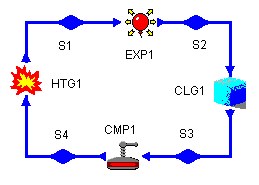
An ideal Diesel cycle with air as the working fluid has a compression ratio of 18 and a cutoff ratio of 2. At the beginning of the compression process, the working fluid is at 14.7 psia, 80ºF, and occupies 117 in3 (0.06771 ft3). The cycle will look like the following:

Determine:
Plot the thermal efficiency of the cycle versus the compression ratio, for compression ratio values from 8 to 25.
Plot the thermal efficiency of the cycle versus the cutoff (expansion) ratio, for cutoff ratio values from 1 to 5.
Save this design and also email it to RoboTA.
Retrieve assignment problem file EX8-3a.PRB.
Directions on how to submit this (.PRB) type of problem
Problem Ex8.3b (based on Example 8.3)
We alter the Diesel cycle from Ex 8.3a to be an Otto cycle with the same heat added during the combustion process as for Problem Ex8.3a and the same compressor inlet conditions.
Recall that the Otto cycle has: constant volume combustion, isentropic expansion, constant volume cooling, and isentropic compression. We don't define a cutoff ratio for an Otto cycle.Plot the thermal efficiency of the cycle versus the compression ratio, for compression ratio values from 8 to 25.
Save this design and also email it to RoboTA.
Retrieve assignment problem file EX8-3b.PRB.
Directions on how to submit this (.PRB) type of problem