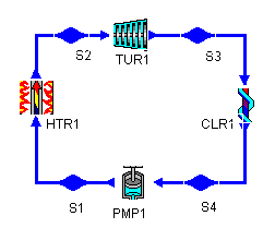
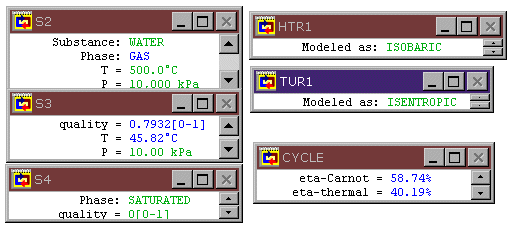
Figure 1: An ideal Rankine Cycle


Figure 1: An ideal Rankine Cycle
Consider the Rankine Cycle shown in Figure 1. While at first glance this appears to be an attractive cycle (a thermal efficiency of 40% is quite good), it has two problems considered as a practical device. First, the pressure ratio assumed across the turbine is unrealistically high (about 1000). Second, the steam coming out of the turbine (at S3) is over 20% wet, which may damage a real turbine.
We could address the pressure ratio problem by splitting the turbine into two sequential turbines, each with a PR of about 32.
The low quality of the steam at the turbine outlet is a more interesting problem, and one that can occur in many vapor power cycles. When the steam at the outlet of a turbine becomes wet, the liquid present is in the form of water droplets. If the steam is not very wet, the amount of water is small and the droplets are not too troublesome to the operation of the turbine. This is because the liquid drops are formed by condensation from the steam to form a kind of fog. Like atmospheric fog, this fog contains extremely small drops and the drops move with almost the same velocity as the surrounding steam.
However, as the quality of the steam decreases, the concentration of these water droplets increases. The turbine blades move rapidly through the steam and tend to collect the water droplets. This is because the denser water droplets do not move with quite the same velocity as the steam, and so get "scooped up" by the blade. Once on the blade, the water forms a film and runs to the back of the blade. Here the water is re-entrained into the steam. But this droplet formation method is completely different to the original one. The droplets are a completely different size: they are much larger and now no longer follow the steam flow. When these large drops impact with the turbine blades they can do much damage and certainly impair the efficiency of the turbine. It is often considered unwise to allow steam with qualities of less than around 85% to 90% to remain in the turbine.
There are two remedies available for this problem.
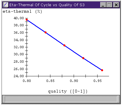
Figure 2: Increasing the quality of the steam at the turbine
outlet leads to decreased efficiency in the Rankine Cycle
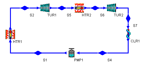
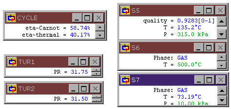
Figure 3: Rankine Cycle with reheat
Note that we also could have designed this statepoint by assuming the outlet quality to be 90%. In that case, our outlet pressure would have been near 179 kPa and the high-pressure turbine's pressure ratio would have been about 56.
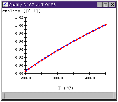
Figure 4: outlet quality vs. reheat temperature
Download the CyclePad design of the Rankine cycle from here, and the Rankine with Reheat cycle from here.
Whalley, P.B. 1992. Basic Engineering Thermodynamics. Oxford University Press. ISBN: 0-19-856255-1
Contributed by: Peter B. Whalley, Kenneth D.
Forbus, M. E. Brokowski
Initial Entry: 9/5/97
Last Edited: 12/9/97
For comments or suggestions please contact cyclepad-librarian@cs.northwestern.edu